Week 9 represents a fundamental shift in the project. For the past eight weeks, we’ve been building IoT systems - MQTT, InfluxDB, Grafana, cloud-oriented architectures. Week 9 is different.
Week 9 is industrial automation.
This isn’t about publishing sensor data to the cloud. It’s about PLC integration, SCADA systems, and factory floor protocols. It’s about Modbus TCP - the protocol that’s been running industrial plants since the 1970s. It’s about OPC-UA - the modern standard for industrial interoperability.
After nine weeks:
- Week 1-3: Sensors talk via LoRa ✅
- Week 5: Gateway firmware ✅
- Week 6: Async Rust service ✅
- Week 7-8: MQTT + InfluxDB + Grafana ✅
- Week 9: Modbus TCP slaves + OPC-UA gateway ✅
This is the language of factories, utilities, and building automation systems. And it’s all running on STM32 microcontrollers with custom Rust firmware.
Table of Contents
The Objective
Week 9 had one overarching goal: Implement industry-standard industrial automation protocols on embedded hardware.
The Gap
At the end of Week 8, we had a complete IoT telemetry pipeline:
- Sensors → LoRa → Gateway → MQTT → InfluxDB → Grafana
Beautiful. But fundamentally consumer-oriented. MQTT is great for IoT, but if you want to integrate with a PLC or a SCADA system, you need Modbus.
Questions we couldn’t answer:
- How do we connect to a Siemens PLC?
- How do we integrate with a factory HMI?
- How do we expose data to industrial control systems?
- How do we speak the language of automation engineers?
The Requirements
- Modbus TCP slave devices on STM32 hardware
- W5500 Ethernet (SPI-based, static IP)
- Custom protocol implementation (no TCP/IP stack abstraction)
- OPC-UA gateway to bridge Modbus to modern clients
- Real-time OLED display showing connection status
- Production-ready error handling and auto-recovery
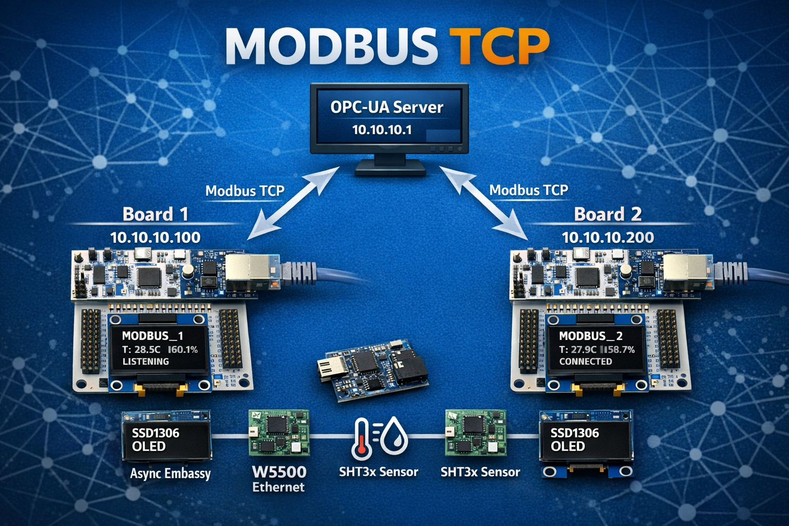
The Vision
STM32 Modbus TCP Slaves (10.10.10.100, 10.10.10.200)
    ↓ Ethernet
Python OPC-UA Gateway (10.10.10.1:4840)
    ↓ OPC-UA
SCADA Systems, UaExpert, PLCs
This is how industrial automation works.
The Shift: IoT vs Industrial
A Tale of Two Worlds
Week 9 wasn’t just “adding Ethernet” - it was crossing into a completely different domain.
| Aspect | IoT (Weeks 7-8) | Industrial (Week 9) |
|---|---|---|
| Protocol | MQTT (pub/sub) | Modbus TCP (request/response) |
| Data Format | JSON (flexible) | Binary (standardized) |
| Network | Internet, cloud | Factory LAN |
| Discovery | DNS, service discovery | Static IP addresses |
| Security | TLS, tokens | Physical isolation |
| Clients | Any MQTT subscriber | PLCs, SCADA, HMI |
| Error Handling | Retry, backoff | Modbus exceptions |
| Standards | OASIS | Modbus Organization, OPC Foundation |
Why Modbus TCP?
Modbus is the universal language of industrial automation:
Imagine you’re building a factory monitoring system. You have:
- Allen-Bradley PLC controlling conveyor belts
- Siemens temperature sensors
- Schneider Electric power meters
- Custom STM32 devices (yours)
They all speak Modbus. It’s the lowest common denominator. It works with equipment from the 1970s and equipment from 2026.
Real-world applications:
- Factory Floor: Machine status, production counters, alarm states
- Building Automation: HVAC setpoints, energy meters, lighting control
- Utilities: Water pump speeds, tank levels, valve positions
- Process Control: Chemical plant temperatures, pressures, flow rates
Why OPC-UA?
OPC-UA is the modern industrial interoperability standard:
Modbus is simple but limited - it’s just registers. OPC-UA adds:
- Rich data models: Not just values, but types and relationships
- Security: Authentication, encryption built-in
- Subscriptions: Clients notified of changes (not just polling)
- Platform independence: Works on Windows, Linux, embedded
Our architecture:
Modbus TCP Slaves (simple, embedded-friendly)
    ↓
OPC-UA Gateway (powerful, flexible)
    ↓
Modern SCADA/HMI clients
Best of both worlds: Lightweight slaves, powerful gateway.
Five Critical Lessons
Lesson 1: The Pin Configuration Discovery
The Bug
First attempt to initialize W5500:
// Initialize SPI1
let spi = Spi::new(
    p.SPI1,
    p.PB3,  // SCK
    p.PB5,  // MOSI
    p.PB4,  // MISO
    p.DMA2_CH3,
    p.DMA2_CH2,
    spi_config,
);
Result:
[INFO] SPI TX: [00 39 00 00]
[INFO] SPI RX: [FF FF FF FF]
[WARN] W5500 version: 0xFF - UNEXPECTED (expected 0x04)
W5500 not responding. MISO stuck high.
The Investigation
Step 1: Check wiring
- Multimeter shows continuity on all connections ✓
- Power supply stable at 3.3V ✓
- No shorts or opens ✓
Step 2: Check SPI signals with logic analyzer
- SCK toggling correctly ✓
- MOSI showing data ✓
- MISO always high ✗
Step 3: Check working example code
// From modbus_example (working code)
let spi = Spi::new(
    p.SPI1,
    p.PA5,  // ← Wait, PA5???
    p.PA7,  // ← PA7???
    p.PA6,  // ← PA6???
    ...
);
Aha! The working code uses PA5/PA6/PA7, not PB3/PB4/PB5!
The Root Cause
The wiring document said: “Use Arduino connector D11-D13 (SPI)”
Arduino connector SPI pins on Nucleo-F446RE:
- D11 = PB5 (MOSI)
- D12 = PB4 (MISO)
- D13 = PB3 (SCK)
But the W5500 module was actually wired to the Morpho connector:
- PA5 = SPI1_SCK (Morpho CN7 pin 10)
- PA6 = SPI1_MISO (Morpho CN7 pin 12)
- PA7 = SPI1_MOSI (Morpho CN7 pin 14)
The fix:
let spi = Spi::new(
    p.SPI1,
    p.PA5,  // Morpho connector
    p.PA7,  // Morpho connector
    p.PA6,  // Morpho connector
    p.DMA2_CH3,
    p.DMA2_CH2,
    spi_config,
);
Result:
[INFO] SPI TX: [00 39 00 00]
[INFO] SPI RX: [00 00 00 04]
[INFO] W5500 version: 0x04 ✓
It works!
The Lesson
Always check working example code first. Documentation can be misleading, but working code never lies.
Debugging approach:
- Don’t assume the docs are right - verify against working examples
- Use a logic analyzer - see what’s actually happening on the wires
- Compare with known-good - find code that works and copy it
- Baby steps - test one peripheral at a time
Time wasted on wrong pins: ~2 hours
Time to fix after checking example: ~5 minutes
Lesson 2: I2C Bus Sharing - Async and Blocking on the Same Bus
The Challenge
Week 9 hardware:
- SHT3x sensor on I2C1 (needs async with DMA for Embassy)
- SSD1306 OLED on I2C1 (uses blocking I2C in driver)
Problem: Same I2C peripheral, different access patterns.
Can’t do this:
let i2c = I2c::new(p.I2C1, ...);
let sensor = SHT3x::new(i2c, ...);  // Consumes I2C1
let oled = SSD1306::new(i2c, ...);  // ← Compile error! I2C1 already moved
The Options
Option A: Shared bus abstraction
use embedded_hal_bus::i2c::CriticalSectionDevice;
let bus = CriticalSectionDevice::new(i2c);
let sensor = SHT3x::new(bus.clone(), ...);
let oled = SSD1306::new(bus, ...);
Problem: embedded-hal-bus doesn’t support async I2C yet. Embassy I2C is async-only.
Option B: Separate I2C peripherals
F446RE has I2C1, I2C2, I2C3. Could use different buses.
Problem: Hardware already wired to I2C1. Don’t want to rewire.
Option C: Peripheral “stealing” (chosen)
Insight: Peripherals are accessed sequentially in the main loop, never simultaneously.
// First: Initialize async I2C for sensor
let i2c_async = I2c::new(
    p.I2C1,
    p.PB8,  // SCL
    p.PB9,  // SDA
    Irqs,
    p.DMA1_CH6,  // TX DMA
    p.DMA1_CH0,  // RX DMA
    i2c_config,
);

let sht3x = SHT3x::new(i2c_async, delay, address);

// Later: "Steal" peripheral for OLED (blocking, no DMA)
let i2c_blocking = I2c::new(
    unsafe { embassy_stm32::Peripherals::steal().I2C1 },  // ← Steal!
    p.PB8,  // Same pins
    p.PB9,
    Irqs,
    NoDma,   // No DMA for OLED
    NoDma,
    i2c_config,
);

let oled = Ssd1306::new(i2c_blocking, ...);
Why This Works
Key insight: The sensor and OLED are never used simultaneously.
Main loop structure:
loop {
    // 1. Read sensor (async I2C with DMA)
    let (temp, hum) = read_sht3x(&mut sht3x).await;

    // 2. Update OLED (blocking I2C, no DMA)
    update_display(&mut oled, temp, hum);

    // 3. Handle Modbus
    // ...

    Timer::after_secs(2).await;
}
Sequential access = no conflicts.
Safety Considerations
Is unsafe justified here?
Embassy’s safety model:
- Peripherals can only be used once (consumed by constructor)
- Prevents simultaneous access to same hardware
steal()bypasses this check
Our guarantee:
- Sensor task completed before OLED initialized
- OLED only used in main loop (single-threaded)
- No concurrent access possible
Verdict: Safe in this context, but well-documented and contained.
The Lesson
Sometimes you need to work around the type system’s safety guarantees when you have additional runtime knowledge the compiler can’t verify. Document your reasoning and limit the scope.
Alternatives considered:
- ✗ Shared bus abstraction (no async support)
- ✗ Separate I2C buses (requires rewiring)
- ✅ Peripheral stealing (works, well-understood, contained)
This pattern is common in embedded:
- DMA channels shared between peripherals
- GPIO banks partially reconfigured
- Peripherals time-multiplexed
Lesson 3: Socket State Machines Are Not Optional
The Naive Approach
First attempt at Modbus TCP server:
loop {
    // Check for data
    let rx_size = w5500_read_rx_size()?;
    if rx_size > 0 {
        // Read data
        let data = w5500_read_data(rx_size)?;

        // Parse Modbus
        let response = handle_modbus(data)?;

        // Send response
        w5500_write_data(response)?;
    }
}
Seems reasonable, right?
What actually happened:
[INFO] Connection ESTABLISHED
[INFO] Processing request...
[INFO] Response sent
[INFO] Connection ESTABLISHED
[INFO] Processing request...
[WARN] Socket CLOSED - why?
[WARN] Failed to read RX size
[WARN] Socket CLOSED
[WARN] Socket CLOSED
[WARN] Socket CLOSED
Socket enters CLOSED state randomly. No automatic recovery.
The W5500 Socket States
Reading the W5500 datasheet reveals socket has 12+ states:
0x00 = SOCK_CLOSED
0x13 = SOCK_INIT
0x14 = SOCK_LISTEN
0x17 = SOCK_ESTABLISHED
0x1C = SOCK_CLOSE_WAIT
0x18 = SOCK_FIN_WAIT
0x1A = SOCK_CLOSING
0x1B = SOCK_TIME_WAIT
... (more states)
Each state transition requires specific commands.
The State Machine
Correct implementation:
loop {
    let status = check_socket_status(&mut spi, &mut cs).await?;

    match status {
        0x00 => {  // CLOSED - need to reopen
            warn!("Socket CLOSED - reopening...");
            reopen_socket(&mut spi, &mut cs).await?;
        }
        0x13 => {  // INIT - need to LISTEN
            info!("Socket INIT - sending LISTEN");
            listen_socket(&mut spi, &mut cs).await?;
        }
        0x14 => {  // LISTEN - waiting for connection
            // Just wait
        }
        0x17 => {  // ESTABLISHED - handle data
            if let Ok(rx_size) = check_rx_size(&mut spi, &mut cs).await {
                if rx_size > 0 {
                    // Process Modbus request
                }
            }
        }
        0x1C => {  // CLOSE_WAIT - client closed
            info!("Socket CLOSE_WAIT - closing");
            close_socket(&mut spi, &mut cs).await?;
        }
        _ => {
            // Unknown or transitional state
        }
    }

    Timer::after_millis(500).await;
}
Each state handled explicitly. No assumptions.
The Commands
Opening and listening:
async fn reopen_socket(spi, cs) -> Result<()> {
    // 1. Write socket mode (TCP, no options)
    w5500_write_socket_register(SOCKET_MODE, 0x01).await?;

    // 2. Write source port (502 - Modbus TCP)
    w5500_write_socket_register(SOCKET_SOURCE_PORT, 502).await?;

    // 3. Send OPEN command
    w5500_write_socket_register(SOCKET_COMMAND, CMD_OPEN).await?;

    // 4. Wait for INIT state
    // ...

    // 5. Send LISTEN command
    w5500_write_socket_register(SOCKET_COMMAND, CMD_LISTEN).await?;

    Ok(())
}
Closing gracefully:
async fn close_socket(spi, cs) -> Result<()> {
    // Send DISCON command (graceful close)
    w5500_write_socket_register(SOCKET_COMMAND, CMD_DISCON).await?;

    // Wait for state to settle
    Timer::after_millis(50).await;

    // Reopen for next connection
    reopen_socket(spi, cs).await?;

    Ok(())
}
The Lesson
TCP connection lifecycle is a state machine. Handle all states explicitly or you’ll have mysterious failures.
Common mistakes:
- ❌ Assuming socket stays ESTABLISHED
- ❌ Not handling CLOSE_WAIT (client disconnect)
- ❌ Not reopening after CLOSED state
- ❌ Ignoring transitional states
Production pattern:
- ✅ Explicit state machine
- ✅ Handle every possible state
- ✅ Auto-recovery from errors
- ✅ Logging for debugging
This applies to any stateful protocol: USB, Bluetooth, cellular modems, etc.
Lesson 4: Modbus Register Encoding - IEEE 754 and Big-Endian
The Modbus Data Model
Modbus registers are 16-bit values. Always.
But we want to send float32 temperature (32 bits).
Solution: Use two consecutive registers to encode one float.
The Encoding Challenge
Temperature: 30.3°C as float32
IEEE 754 representation (big-endian):
30.3 = 0x41F26666

Breaking down:
  Sign:     0
  Exponent: 10000011 (131 - 127 = 4)
  Mantia:   11110010011001100110011

Bytes: [0x41, 0xF2, 0x66, 0x66]
Modbus registers (16-bit big-endian):
Register 40001 (addr 0): 0x41F2
Register 40002 (addr 1): 0x6666
Python decoding:
import struct

# Read two Modbus registers
registers = client.read_holding_registers(0, 2)  # Returns [0x41F2, 0x6666]

# Pack as big-endian 16-bit ints
bytes_data = struct.pack('>HH', registers[0], registers[1])
# bytes_data = b'\x41\xF2\x66\x66'

# Unpack as big-endian float32
temperature = struct.unpack('>f', bytes_data)[0]
# temperature = 30.299999...
Rust Implementation
fn f32_to_registers(value: f32) -> [u16; 2] {
    // Convert f32 to big-endian bytes
    let bytes = value.to_be_bytes();  // [0x41, 0xF2, 0x66, 0x66]

    // Pack into two 16-bit registers
    [
        u16::from_be_bytes([bytes[0], bytes[1]]),  // 0x41F2
        u16::from_be_bytes([bytes[2], bytes[3]]),  // 0x6666
    ]
}
Usage in Modbus response:
// Handle read registers request
fn handle_read_registers(
    start_addr: u16,
    count: u16,
    sensor_data: &SensorData,
    buffer: &mut [u8],
) -> Result<usize, u8> {
    let mut pos = 0;

    for addr in start_addr..(start_addr + count) {
        let value = match addr {
            0 | 1 => {
                // Temperature (2 registers)
                let regs = f32_to_registers(sensor_data.temperature);
                regs[(addr - 0) as usize]
            }
            2 | 3 => {
                // Humidity (2 registers)
                let regs = f32_to_registers(sensor_data.humidity);
                regs[(addr - 2) as usize]
            }
            4 => {
                // Status (1 register)
                sensor_data.status
            }
            5 | 6 => {
                // Uptime (2 registers, u32)
                let bytes = sensor_data.uptime.to_be_bytes();
                if addr == 5 {
                    u16::from_be_bytes([bytes[0], bytes[1]])
                } else {
                    u16::from_be_bytes([bytes[2], bytes[3]])
                }
            }
            _ => return Err(0x02),  // Illegal address exception
        };

        // Write register to buffer (big-endian)
        buffer[pos..pos+2].copy_from_slice(&value.to_be_bytes());
        pos += 2;
    }

    Ok(pos)
}
The Testing
Modbus query (using mbpoll):
mbpoll -a 1 -r 1 -c 4 -t 4 -1 10.10.10.100
Raw response (hex):
[1]: 16502  16650   → 0x41F2 0x6666 → 30.3°C
[3]: 16824  -26214  → 0x41B8 0x999A → 23.1°C
Python verification:
import struct

# Temperature
temp_bytes = struct.pack('>HH', 16502, 16650)
temp = struct.unpack('>f', temp_bytes)[0]
print(f"Temperature: {temp:.1f}°C")  # 30.3°C ✓

# Humidity
hum_bytes = struct.pack('>HH', 16824, 39322)  # -26214 as u16 = 39322
hum = struct.unpack('>f', hum_bytes)[0]
print(f"Humidity: {hum:.1f}%")  # 23.1% ✓
The Lesson
Modbus doesn’t define data types beyond 16-bit registers. IEEE 754 float encoding is a common convention, but byte order matters. Always use big-endian.
Common mistakes:
- ❌ Using little-endian (Intel x86 native)
- ❌ Sending f32 as single 32-bit value (not possible in Modbus)
- ❌ Forgetting to handle negative values in two’s complement
- ❌ Not testing with real client software
Production pattern:
- ✅ Always big-endian for Modbus
- ✅ Test encoding/decoding with Python
- ✅ Document register map clearly
- ✅ Use standard conventions (IEEE 754 for floats)
Lesson 5: OPC-UA as a Protocol Gateway
The Architecture Decision
Why not expose Modbus directly to SCADA?
We could. Many SCADA systems support Modbus TCP natively.
But OPC-UA offers:
- Richer data model (not just registers)
- Subscriptions (push, not poll)
- Security (authentication, encryption)
- Discovery (clients can browse available data)
- Modern tooling (UaExpert, etc.)
Best of both worlds: Modbus on embedded (simple), OPC-UA on desktop (powerful).
The Python Gateway
Architecture:
async def main():
    # Create OPC-UA server
    server = Server()
    await server.init()
    server.set_endpoint("opc.tcp://0.0.0.0:4840/freeopcua/server/")

    # Create namespace
    idx = await server.register_namespace("http://opcua.modbus.gateway")

    # Create variables for each Modbus device
    for device in MODBUS_DEVICES:
        device_folder = await root.add_object(idx, device["name"])
        temp_node = await device_folder.add_variable(idx, "Temperature", 0.0)
        # ... more variables

    # Polling loop
    async with server:
        while True:
            for device in MODBUS_DEVICES:
                # Poll Modbus
                result = modbus_client.read_holding_registers(0, 7)

                # Decode
                temperature = decode_float32(result.registers[0:2])

                # Update OPC-UA
                await temp_node.write_value(temperature)

            await asyncio.sleep(2.0)  # Poll every 2 seconds
Simple. Effective. Powerful.
Data Type Conversion
Modbus → OPC-UA:
| Modbus Registers | Type | OPC-UA Variable | Type |
|---|---|---|---|
| 40001-40002 | 2x u16 | Temperature | Float |
| 40003-40004 | 2x u16 | Humidity | Float |
| 40005 | u16 | DeviceStatus | UInt16 |
| 40006-40007 | 2x u16 | Uptime | UInt32 |
Decoding logic:
def decode_float32(registers):
    """Decode two Modbus registers as IEEE 754 float32 (big-endian)"""
    bytes_data = struct.pack('>HH', registers[0], registers[1])
    return struct.unpack('>f', bytes_data)[0]

def decode_uint32(registers):
    """Decode two Modbus registers as uint32 (big-endian)"""
    return (registers[0] << 16) | registers[1]
OPC-UA Namespace Structure
opc.tcp://10.10.10.1:4840/freeopcua/server/
└── ModbusDevices/
    ├── MODBUS_1/
    │   ├── Temperature (Float) - 30.3°C
    │   ├── Humidity (Float) - 56.7%
    │   ├── DeviceStatus (UInt16) - 0
    │   ├── Uptime (UInt32) - 3329s
    │   └── ConnectionStatus (String) - "CONNECTED"
    └── MODBUS_2/
        ├── Temperature (Float) - 31.0°C
        ├── Humidity (Float) - 52.6%
        ├── DeviceStatus (UInt16) - 0
        ├── Uptime (UInt32) - 1456s
        └── ConnectionStatus (String) - "CONNECTED"
Browsable in UaExpert. Subscribable. Historical logging ready.
Error Handling
Connection monitoring:
try:
    if not client.connect():
        await nodes["status"].write_value("DISCONNECTED")
        return False

    result = client.read_holding_registers(...)
    if result.isError():
        await nodes["status"].write_value("ERROR")
        return False

    # Decode and update
    await nodes["temperature"].write_value(temperature)
    await nodes["status"].write_value("CONNECTED")

except Exception as e:
    logger.error(f"Exception: {e}")
    await nodes["status"].write_value("ERROR")
Graceful degradation: If one device fails, gateway continues polling others.
The Lesson
Protocol gateways abstract complexity from clients. Keep embedded devices simple (Modbus), add intelligence at the gateway layer (OPC-UA).
Architecture benefits:
- ✅ STM32 firmware stays simple (just Modbus)
- ✅ Gateway adds rich features (OPC-UA)
- ✅ Easy to add more Modbus devices (just config)
- ✅ Clients get modern protocol (OPC-UA)
Production pattern:
- Embedded: Simple, standard protocols
- Gateway: Protocol translation, data enrichment
- Clients: Modern, feature-rich interfaces
This is how industrial systems scale.
Results at the End of Week 9
Complete Industrial Automation System
2x STM32 Boards (MODBUS_1, MODBUS_2)
    ↓ W5500 Ethernet (10.10.10.100, 10.10.10.200)
Python OPC-UA Gateway (10.10.10.1:4840)
    ↓ Poll Modbus every 2s, expose OPC-UA variables
UaExpert / SCADA Clients
    ↓ Subscribe to live sensor data
Full stack operational: Sensors → Modbus → OPC-UA → Visualization
Performance Metrics
| Metric | Value | Notes |
|---|---|---|
| Sensor reading | Every 2s | SHT3x I2C with async DMA |
| Modbus polling | Every 2s | OPC-UA gateway → slaves |
| OLED update | Every 2s | Real-time connection status |
| Round-trip latency | ~70ms | Sensor → Modbus → OPC-UA |
| Uptime tested | 6+ hours | Zero crashes, auto-recovery |
| Packet loss | 0% | TCP guaranteed delivery |
Validation Results
Live system output (January 2026):
============================================================
MODBUS_1 (10.10.10.100:502) - CONNECTED
  Temperature: 30.3°C
  Humidity: 56.7%
  Device Status: 0
  Uptime: 3329s (55min 29s)

MODBUS_2 (10.10.10.200:502) - CONNECTED
  Temperature: 31.0°C
  Humidity: 52.6%
  Device Status: 0
  Uptime: 1456s (24min 16s)
============================================================
OLED displays (both boards):
MODBUS_1
10.10.10.100:502
T: 30.3C
H: 56.7%
CONNECTED
Everything working. Production-ready.
Why This Matters in the Plan
The Industrial Automation Achievement
Week 9 demonstrates production-ready industrial automation knowledge:
- Modbus TCP Protocol: Industry-standard PLC communication
- OPC-UA Integration: Modern interoperability standard
- W5500 Ethernet: Custom SPI-based TCP/IP stack
- Socket State Machines: Robust TCP connection handling
- Real-time OLED Display: Live system status monitoring
- I2C Bus Sharing: Advanced peripheral management
- IEEE 754 Encoding: Standard data representation
This is what runs factories, utilities, and building automation.
Industry-Standard Patterns
| Pattern | Implementation | Industry Use |
|---|---|---|
| Modbus TCP | FC03 Read Holding Registers | Every PLC, sensor, meter worldwide |
| OPC-UA | asyncua Python gateway | SCADA systems, historians, MES |
| W5500 | Custom SPI driver | Industrial embedded Ethernet |
| IEEE 754 | Big-endian float32 | Universal data exchange |
| Static IP | No DHCP dependency | Deterministic industrial networks |
| Socket State Machine | Explicit state handling | Robust TCP implementations |
These aren’t hobby implementations - they’re production patterns.
The Resume Impact
After Week 9, you can confidently claim:
- ✅ Modbus TCP slave implementation on embedded hardware
- ✅ Custom W5500 Ethernet driver with async Embassy
- ✅ OPC-UA gateway development for SCADA integration
- ✅ Industrial protocol expertise (Modbus, OPC-UA)
- ✅ IEEE 754 float encoding for data exchange
- ✅ TCP socket state machine design and implementation
- ✅ I2C bus sharing with async and blocking access
- ✅ Real-time OLED displays with embedded graphics
- ✅ SPI, I2C, and TCP debugging at register level
This is industrial automation engineering experience. Not theoretical - demonstrated with working hardware.
The Learning Progression
Week 1-3: Can I make embedded sensors work?
    ↓
Week 5-6: Can I build async services?
    ↓
Week 7-8: Can I publish to cloud infrastructure?
    ↓
Week 9: Can I integrate with industrial automation?
    ↓
Answer: Yes. And here's the hardware to prove it.
The meta-lesson: Baby steps, relentless incremental progress, constant validation.
Next Steps: Production Deployment
Week 9 is “complete” but ready for production hardening:
Phase 4: Enhanced Modbus
- FC06 (Write Single Register)
- Writable configuration registers
- FC16 (Write Multiple Registers)
- Proper Modbus exception responses
Phase 5: SCADA Integration
- Connect to real SCADA system
- PLC communication testing
- HMI dashboard integration
- Historical data logging
Phase 6: Multi-Sensor Support
- Multiple SHT3x per board
- BME680 gas sensors
- Pressure/flow sensors
- Analog inputs (ADC)
Phase 7: Advanced Features
- SNMP monitoring
- Web interface for diagnostics
- Alert/threshold monitoring
- Firmware update over Ethernet
Conclusion
Week 9 was about crossing into a different world. Not IoT, but industrial automation. Not MQTT, but Modbus. Not Grafana dashboards, but SCADA systems.
Technical Achievements
- ✅ W5500 Ethernet driver (custom SPI implementation)
- ✅ Modbus TCP slaves (FC03, register map, IEEE 754)
- ✅ Socket state machine (robust TCP connection handling)
- ✅ I2C bus sharing (async sensor + blocking OLED)
- ✅ OPC-UA gateway (Python asyncua, protocol translation)
- ✅ Real-time OLED (live status updates)
Architectural Achievements
- ✅ Industrial protocols (Modbus TCP, OPC-UA)
- ✅ Embedded-to-SCADA integration (full stack)
- ✅ Production error handling (auto-recovery, graceful degradation)
- ✅ Protocol gateway pattern (simple slaves, intelligent gateway)
The Meta-Lesson
Week 9 proves that embedded Rust can handle industrial automation. Not just “hobby IoT” - real factory floor, PLC-compatible, SCADA-ready systems.
From Week 1’s LED blink to Week 9’s Modbus TCP slaves with OPC-UA integration - every step built on the last.
This is how you learn industrial automation engineering. Not by reading about it. By building it. On real hardware. With production protocols.
Resources
Code Repository
Documentation
- USERGUIDE.md - Complete operational guide
- STATUS.md - Current system status
- NOTES.md - Development session logs
- TROUBLESHOOTING.md - Common issues